Latency Contributors?

Internet Speed and Latency by Country

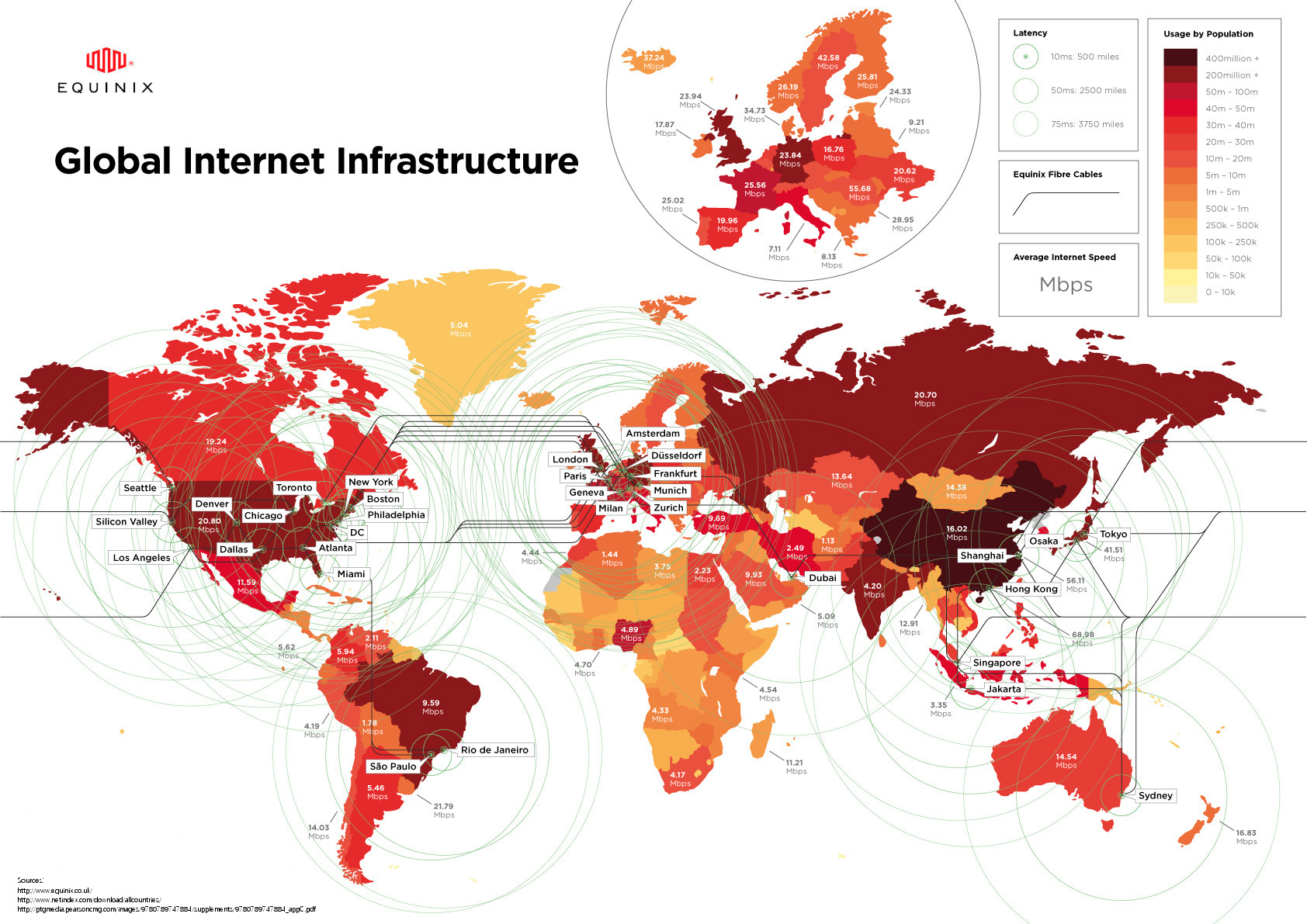
Latency is a time it takes for a bit of data to travel across the network from one node or endpoint to another before the receiver processes the information.

Latency Contributors

  1. Serialization delay
  2. Propagation delay
  3. Packet Switching
  4. Queueing
  5. Packet Drop
  6. Processing

What steps can be taken to reduce latency?

  1. Speed / Bandwidth – Bigger the network pipe lower will be the latency. Latency on a 1G network will be way higher than the 40G network. (Serialization delay)
  2. Media Type / Distance – Passive Twinax CX-1 (SFP+) cables are fastest when compared to Fiber Optic and Copper RJ-45 (CX-1 cable > 5m are consider active). Microwave are faster than Fiber Optic (Propagation delay)
  3. Switching mode – Cut-through provides deterministic latency, store and forward latency is lowest when the packet size is smaller. (Store and forward provide better latency number’s when the packet size is between 64 & 512). (Packet Switching)
  4. Buffer Amount – You need to consider buffer amount when you have speed mismatch on the network or you have many to once conversation. (Queueing & Packet Drops)
  5. Feature Set – Only enable required features to reduce latency. (Processing)

** N3548 has no latency impact regardless of features used

  1. Network Design – Spine and Leaf (Best for East / West Traffic) vs Traditional Hierarchical Architecture (Best for North / South Traffic)
  2. The Compute (Server Type) – Rack Servers are better than chassis base. CPU / Memory Type and Number. (Processing)
  3. The Adapter – Network Adapter with onboard CPU are faster. (Processing)
  4. Security – Hardware features (ACLs, PVLAN) and OS level security is better than firewall appliance from latency point of view. (Processing)

How to calculate Latency on different type of network devices.

Store & Forward Devices: The time interval starting when the last bit of the input frame reaches the input port and ending when the first bit of the output frame is seen on the output port.

Cut-Through Devices: The time interval starting when the end of the first bit of the input frame reaches the input port and ending when the start of the first bit of the output frame is seen on the output port.

Reference

BRKDCT-2214 – Ultra Low Latency Data Center Design – End-to-end design approach (Cisco Live)

RFC 1242, 2544, 2889, 391

RP Deployment methods.

Static RP

This method is not scalable (manual configuration required on every router in the multicast domain) and does not provide redundancy or load-balancing.

Bootstrap Router (BSR)

  • Open Standard.
  • The function of the BSR is to broadcast the RP set to all routers in the domain.
  • It ensures that all routers in the PIM domain have the same RP cache as the BSR.
  • It is possible to configure the BSR to help select an RP set from BSR candidate RPs.
  • BSR messages are flooded hop-by-hop throughout the entire network.
  • Use ip pim bsr-border command on the edge router connecting to MSDP domains.

Auto-RP

  • Cisco Proprietary
  • Auto-RP automates the distribution of group-to-RP mappings. (Multicast is used for distribution)
  • Auto-RP supports the use of multiple RP’s within a network to server different group ranges and allows configurations of redundant RPs.
  • Auto-RP mechanism operates using two basic components.
    • Candidate RPs advertise their willingness to be an RP via “RP-announcement”
      • CISCO-RP-ANNOUNCE = 224.0.1.39
    • RP mapping agents join group and map the RPs to the associated groups.
      • CISCO-RP-DISCOVERY = 224.0.1.40
  • Because multicast is used to distribute this information it requires Dense mode for scalability or use ip pim autorp listener along with access-list command to put the spare mode interface in dense mode for two Auto-RP groups (224.0.1.39 & 224.0.1.40)

Anycast-RP

  • Anycast RP provides for fast failover of IP multicast and allows for load-balancing.
  • Two or more RPs are configured with the same IP address on loopback interfaces. The Anycast RP loopback address should be configured with a 32-bit mask.
  • MSDP is the protocol used by RPs to share information about active sources.
  • You can use BSR or Auto-RP to automate RP distribution.

Phantom RP

  • Phantom RP provides for fast failover of IP multicast but no load-balancing.
  • Two or more RPs are configured with the same IP address on loopback interfaces, but with different mask length.
  • You can use BSR or Auto-RP to automate RP distribution.
  • This is only option to configure Bidir PIM redundancy.

Embedded RP

  • As the name states embedded RP defines an address allocation policy in which the address of the RP is encoded in an IP multicast group address.
  • Support’s only IPv6 and Source-Specific multicast.

Comparison of RP Mechanisms

Static RP BSR Auto-RP Embedded RP
Must be configured on every router Yes No (except on candidate-BSRs and candidate-RPs) No (except on candidate RPs and mapping agents) No (except RP routers)
Supports IPv4 addresses Yes Yes Yes No
Supports IPv6 addresses Yes Yes No Yes
RP redundancy No (unless used with Anycast RP) Yes Yes No

Reference

Multicast Resource Calculation

Multicast memory usage calculation (formula).

  1. Each (*.G) entry requires 380 bytes + outgoing interfaces list (OIL) overhead.
  2. Each (S,G) entry requires 220 bytes + outgoing interface list overhead.

**The outgoing interface list overhead is 150 bytes per OIL entry.

For example, if there are 10 groups with 6 sources per group and 3 outgoing interfaces:

10 x (380 + (3 x 150)) = 8,300 bytes for (*.G)

60 x (220 + (3 x 150)) = 40,200 bytes for (S,G)

A total of 48,500 bytes of memory is required for the mroute table.

Reference

Protocol Independent Multicast (PIM) Models

Source Tree
Source Tree
Shared Distribution Tree

PIM Dense Mode (PIM DM) – Push Model

  • Routers configured for PIM DM mode initially flood multicast traffic out of all interfaces.
  • Neighbor that do not have members send Prune messages toward the source to prune off the unwanted traffic. Prune messages timeout’s after three minutes and traffic is re-flooded to all the neighbors.
  • In PIM Dense mode, the control plane and the data plane are the same. Requires plentiful of bandwidth due to re-flooding.
  • Dense mode only has sources trees – no shared threes are used.

PIM Sparse Mode – Explicit join Model

  • Widely used for one-to-many application.
  • PIM Sparse mode uses the explicit join model where receivers send PIM Join messages to a designated RP.
  • Used shared tree from RP to the source and source tree from receiver to RP.
  • Last hop routers may be configured with an “SPT-Threshold” which, once exceeded, will cause the last hop router to join the “Shortest Path Tree” (SPT) up to the source. Default SPT-Threshold value = 0 (Cisco), if configured for infinity it will not use SPT.
  • SPT uses most optimal path to deliver the multicast traffic.
  • In networks with large numbers of senders, an increased amount of state must be kept in the routers. (Increase in memory usage / control plane)
  • Uses Reverse Path Forwarding (RPF) check to avoid multicast routing loops
  • MSDP is used for inter-domain multicast.

 Source-Specific Multicast

  • Utilizes all the benefits of spare mode protocols but eliminates shared trees.
  • Allows only one source per group.
  • No RP required. Receive is aware about multicast source. Work’s with IGMPv3 only.
  • Does not need MSDP for inter-domain multicast.

Bidirectional PIM

  • Widely used for many-to-many application.
  • Use the same shared tree for traffic from sources towards RP and from RP to receivers.
  • Less state in routers (Better performance / easy on control plane)
  • You can run into suboptimal multicast traffic delivery.
  • Violates RPF rules which can lead to multicast routing loops.
  • Only Phantom RP can be used for RP redundancy.

What is Multicast?

Unicast_Multicast

Multicast is a mechanism where host transmitting a single copy of data to a multicast group, and multicast routers replicates to all the branches where receivers exist.

Multicast Applications

  1. One-to-many
  2. Many-to-many
  3. Many-to-one (rarely used)

Internet Group Management Protocol (IGMP) permit’s hosts to communicate their desire to receive multicast traffic to the multicast router on the LAN.

IGMP Versions

  1. IGMPv1 (old)
  2. IGMPv2
  3. IGMPv3 (design to work with Source-Specific Multicast)

Protocol-Independent Multicast (PIM) is a family of multicast routing protocols for IP networks. Although PIM is called a multicast routing protocol, it actually uses the unicast routing table to perform the revers path forwarding (RPF) check. PIM can leverage any unicast routing protocols.

PIM has four different configuration options

  1. PIM Dense Mode (rarely used – no RP required)
  2. PIM Sparse Mode
    • Spare Mode
    • Bidirectional PIM (Best for Many-to-Many applications)
    • PIM Source-Specific Multicast

A Rendezvous Point (RP) is a router in a multicast network domain that acts as a shared root for a multicast shared tree.

A Designated Router (DR) is a router that will forward the PIM join message from the receiver to the RP.

A Designated Forwarder (DF) is a router that decide what packets need to be forwarded upstream toward the rendezvous point. (Used by Bidir PIM)

RP Deployment methods

  1. Static RP
  2. Bootstrap Router (BSR)
  3. Auto-RP
  4. Anycast-RP
  5. Phantom RP
  6. Embedded RP

Interdomain Multicast

Multiprotocol BGP (MBGP) + Multicast Source Discovery Protocol (MSDP)

PIM spare mode is used within a domain, domains are connected using MBGP (to exchange unicast routing table) and MSDP is used to peer between two RP’s in respective domain to exchange active source registered to RP’s in their respective domains.

**Be aware of multicast address overlap.

GUIDELINES FOR ENTERPRISE IP MULTICAST ADDRESS ALLOCATION

Internet Protocol version 6 (IPv6)

IPv6 uses a 128-bit address in contrast to IPv4 32-bit address.

IPv6 addresses are represented as eight groups of four hexadecimal digits separated by colons.

IPv6 Adoption

IPv4 Exhaustion

IPv6 Address Planning

  • It is strongly recommended that all IPv6 subnets use a /64 prefix.
  • When using /126 prefixes, avoid overlap with router anycast and embedded RP addresses.

Design Options for IPv6 in Campus Network

  1. Dual-Stack Model
    >> This model deploys IPv4 and IPv6 in parallel without any tunneling or translation between the two protocols.
  2. Hybrid Model
    >> The hybrid model uses dual stack in all areas of the network where the equipment supports IPv6.
    >> Tunneling mechanisms are deployed for areas that do not currently support Ipv6.
  3. Service Block Model
    >> Service block model centralized IPv6 connectivity through a separate redundant pair of switches.
    >> The underlining IPv4 network is used as the foundation for the overlay IPv6 network that is deployed.
    >> Tunnels are utilized from the data center aggregation layer to provide IPv6 access to the applications and services that are located in the data center access layer.
    >> IPv4 routing is configured between the core layer and service block switches to allow visibility to the services block (IPv6) switches for terminating IPv6 in IPv4 tunnels.

Design Options for IPv6 MPLS
Many migration approaches are available to a service provider to all IPv6 services to its current services portfolio. Out of all option following two option are best. (Scalable, no upgrade to P routers & gradual deployment.

  1. IPv6 Provider Edge (6PE)
    >> PE routers are dual-stack.
    >> The 6PE solution uses this same transparent routing and transport to achieve global IPv6 reachability over an IPv6 unaware IPv4 MPLS backbone.
    >> IPv6 & IPv4 support on access interface (client facing).
    >> Only IPv4 support to the interface facing core (connecting to P router).
    >> The reach-ability information advertised among PE routers via MP-BGP is no longer IPv4 VPN prefixes but rather IPv6.
  2. IPv6 VPN Provider Edge (6VPE)
    >> Extensions to the 6PE approach
    >> Uses different address family in MP-BGP defined for the 6VPE purpose, which is the VPN-IPv6 address family.
    >> Uses VRF concept to separate customer routers.

Cisco Adaptive Security Virtual Appliance (ASAv10 / ASAv30) + vCenter Site Recovery Manager (SRM)

3 Things to keep in mind when building SRM plan for Cisco virtual ASAv10 & ASAv30 Firewalls.

  • Make sure you allocate right number of minimum and maximum CPU (command: show vm can be used to validate the configuration).
  • Instead of powering off, select option (or configure) to disconnect Virtual Firewall.
  • Configure to skip “vm tools” install.

**You cannot SRM ASA 1000v firewall.

Routing Protocol Tips!

  • If using multiple points for redistribution between different IGP protocols makes sure to use filters or route tag.
  • BFD is the best solution for fast failure detection for the neighbours (routing) which are not using point-to-point links.
  • For optimal routing, reduce the routing table / database by summarization or filtering at correct place.
  • Always keep in mind to double check for unknowingly created routing black holes after route summarization, has summarization creates null routes automatically. (For OSPF you can disable creation of null routes by command “no discard-route”).
  • Layer 3 Designs document should include points or remarks where summarization, filtering or redistribution is done along with the router type (e.g. Stub, ABR, ASBR etc.).

EIGRP

  • Best suited for Hub and Spoke Design.
  • Reduce query domains by configuring route summarization or filtering.
  • Configure spoke / remote edge routes has stub router if possible (for dual home sites you can use leak-map to configure them has stub).
  • Try not to have more than 3 or 4 feasible successor.

**EIGRP router reflect (Over the Top)

OSPF

  • Make sure Area 0 is contiguous if not use virtual link’s (if no other alternative then only use virtual links to interconnect area 0).
  • Try to configure stub area where ever design allows.
  • Try to use partial SPF @ Edge / Leaf Nodes.
  • Incremental SPF, SPF Run Time, Event Propagation Time, LSA timers (throttle lsa all, arrival etc.).
  • Link State Loop Free Alternatives.
  • Use OSPF priority instead of router ID for DR election process.

IS-IS

  • If planning to have single IS-IS domain design then go for L2 domain (L2 give flexibility for future redesign).
  • L2 domain need’s to contiguous (same has OSPF area 0).
  • L1 domain contains intra intra area routes, default route advertised by L2 domain and redistributed routes (similar to OSPF NSSA).
  • If you are redistributing IS-IS into any routing protocol and if you have connected interface advertised only to IS-IS it will not redistribute connected interface route.
  • If you are running MPLS make sure to use metric-style wide. If you are in a transition process use metric-style transition.
  • IS-IS prefix prioritization is one of the tools you can use for fast convergence.
  • Consider IS-IS mesh-group option for a fully mesh network running IS-IS
  • IS-IS DIS is similar to OSPF DR (Diff: IS-IS don’t have backup DIS while OSPF has backup DR router)

BGP

  • Reason to use BGP should be to break complexity into smaller pieces not because of excessively huge routing table / database.
  • BGP will be able to handle the huge amount of routes but it will not address underline issue if selection of BGP was done to just overcome the size of the routing table.
  • Routes learned from an eBGP peer propagated to all peers.
  • Routes learned from iBGP peer propagated only to eBGP peers.
  • Locally generated routes propagated to all peers.
  • iBGP cannot detect routing loops within an AS.
  • For smaller iBGP networks with limited growth, iBGP full mesh is easy and cleaner solution.
  • If using loopback address to form eBGP neighbours don’t forget ebgp-multihop.
  • Use route dampening and peer group has per your requirements. (peer group help if sending same advertisement to all peer’s)
  • Load Sharing for eBGP routes
    • Outbound
      • Two Static routes for same subnet or default pointing to different neighbour (next hop IP)
      • Best route selection on base of BGP attributes for each prefix.
      • Accept partial table, to accept only those routes from each provider that are directly attached to them.
    • In-bound
      • AS path prepend
      • Set MED outbound
      • Set communities (will need to get ISP involved to route traffic has per community value)

**Last two only apply if you are dual-homed to the same provider.

  • Alternate to iBGP full mesh
    • Confederations
      • Recommended to deploy when you building a brand new network
      • Will required extended amount of outage window if configured / deployed on existing network running IGP or iBGP mesh.
      • Sub-AS are treated as eBGP neighbours (local pref, MED & next hop is unchanged between sub-AS).
    • Route Reflectors
      • Place router reflectors in flow of physical topology.
      • You can place RR out of flow of physical topology in certain exceptions such has when packet forwarding is achieved through label switching or IP tunneling
      • Easy to deploy with minimum outage window if configured / deployed on existing network running IGP or iBGP mesh.
      • Originator id & Cluster list are used for loop prevention.
      • Cannot modify path attributes for iBGP learned routes when exchanging routing information to other iBGP peers / clients.

What is Confederations?

Confederation is one of the method to reduce number of iBGP neighbors (or get away from full iBGP mesh)

  • Confederations make the network look like one AS to the eBGP peers.
  • The AS is divided into pieces, and each piece is its own AS (private AS)
  • The iBGP peers are the other BGP speakers in the same sub-AS, whereas the eBGP peers are the BGP speakers in the other sub-autonomous systems and outside the main AS.

Advantages

  • Better control of the policies within the network. (A sub AS can be fully mesh or can even have a route reflector)
  • Easy to deploy / configure when build a network from scratch.

Note:

  • Improper or misconfigured confederation can cause routing loops.
  • At all times, each member of a confederations should know what the real ASN is, which sub-autonomous system it belongs to, and what other sub-autonomous systems belong to the same confederation.
  • Local preference and MED are pass along with NEXT_HOP is unchanged between sub-autonomous systems.

Confederation

What is Router Reflector?

Rule: “iBGP peers cannot advertise routes learned from iBGP peers to other iBGP peers”, does not apply to router reflector.

  • A router is configured as a router reflector, and the other iBGP routers, known as clients, peer with the router reflector only. A router reflector and its clients are known collectively as a cluster.
  • Router reflector can peer with both iBGP (client, non-client) and eBGP outside the cluster.
  • Route reflector offer an alternative to fully meshed iBGP peers.

Route Reflections Rules

  • If the route was learned from a non-client iBGP peer, it is reflected to clients only.
  • If the route learned from a client or eBGP peer, it is reflected to all non-clients and clients.

Route Reflector Loop Prevention

  1. ORIGINATOR_ID (it will carry the ROUTER_ID of the originator of the route in the local AS)
  2. CLUSTER_LIST (when a RR reflects a route from its clients to a non-client peer, it must append the local CLUSTER_ID to the CLUSTER_LIST)

Note:

  • To avoid possible routing loops or other routing errors, the router reflector could not change the BGP path attributes.
  • When exchanging internal routing information between RRs and clients and non-clients. RR can modify BGP path attribute, NEXT_HOP for eBGP learned routes send to its internal peers.
  • A rule of thumb is to place RR in flow of physical topology. In other words, define the iBGP peering to match the physical / topology connectivity of the network. (in-path)
  • You can place RR out of flow of physical topology in certain exceptions such has when packet forwarding is achieved through label switching or IP tunnelingRR1
  • RR2